


OLYCOM
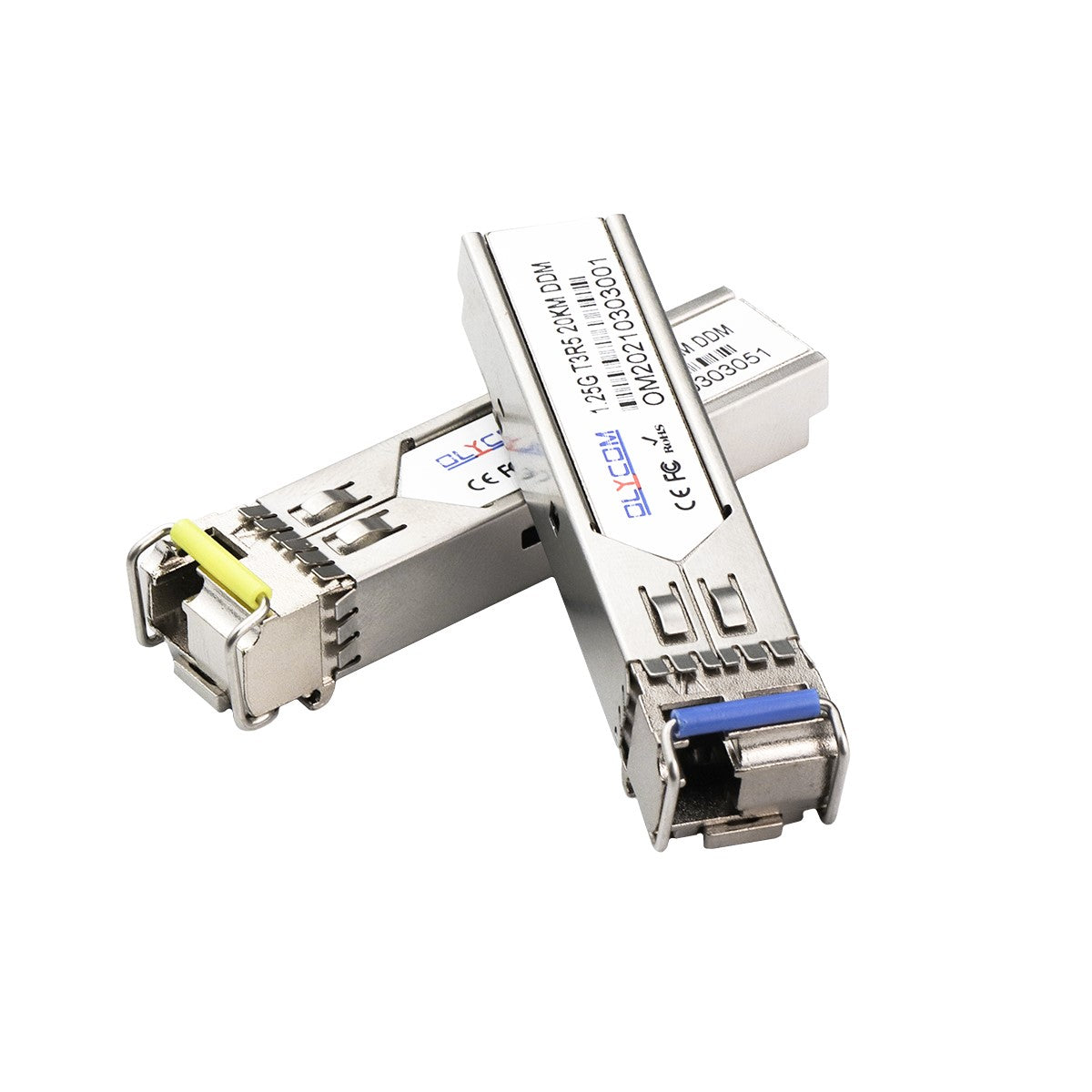
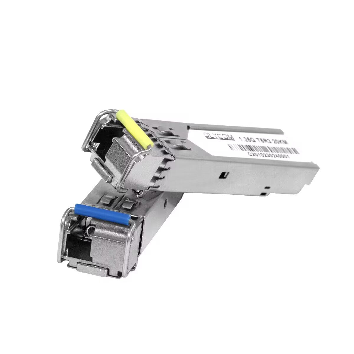
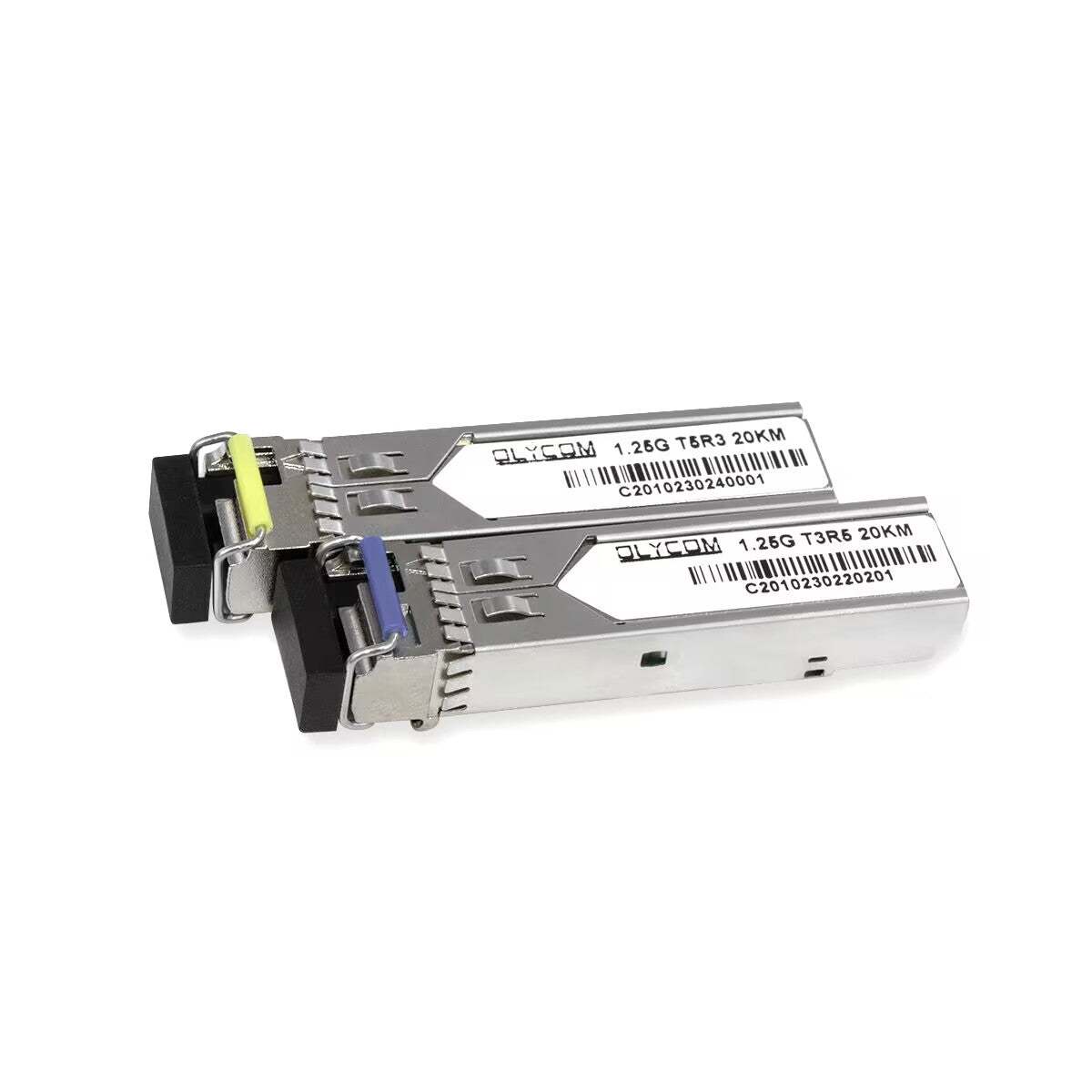
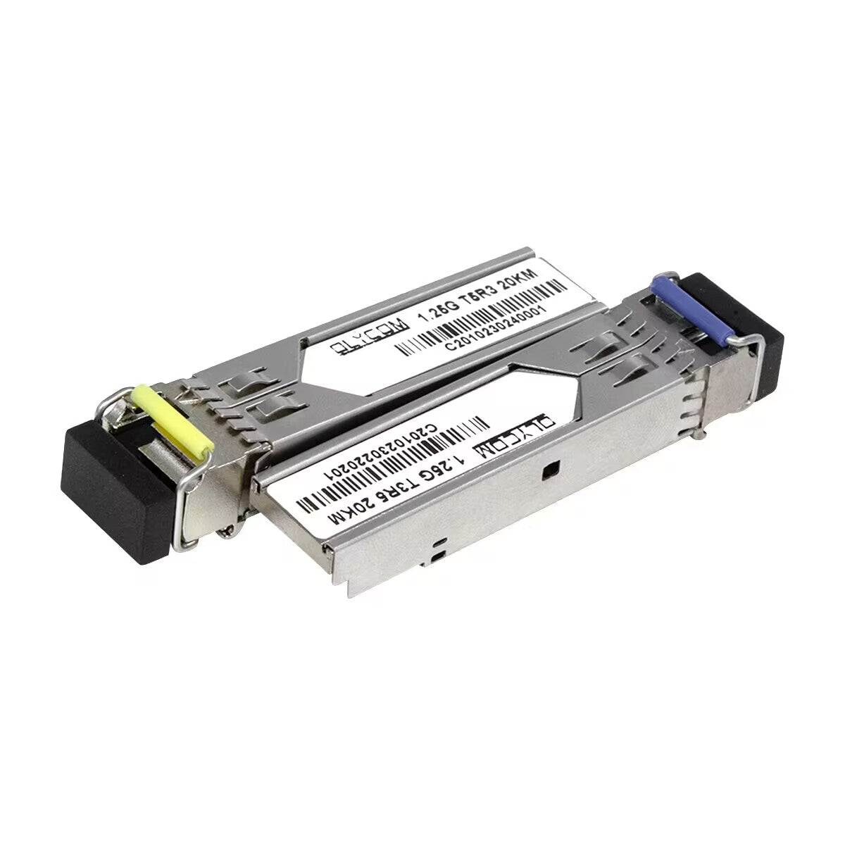
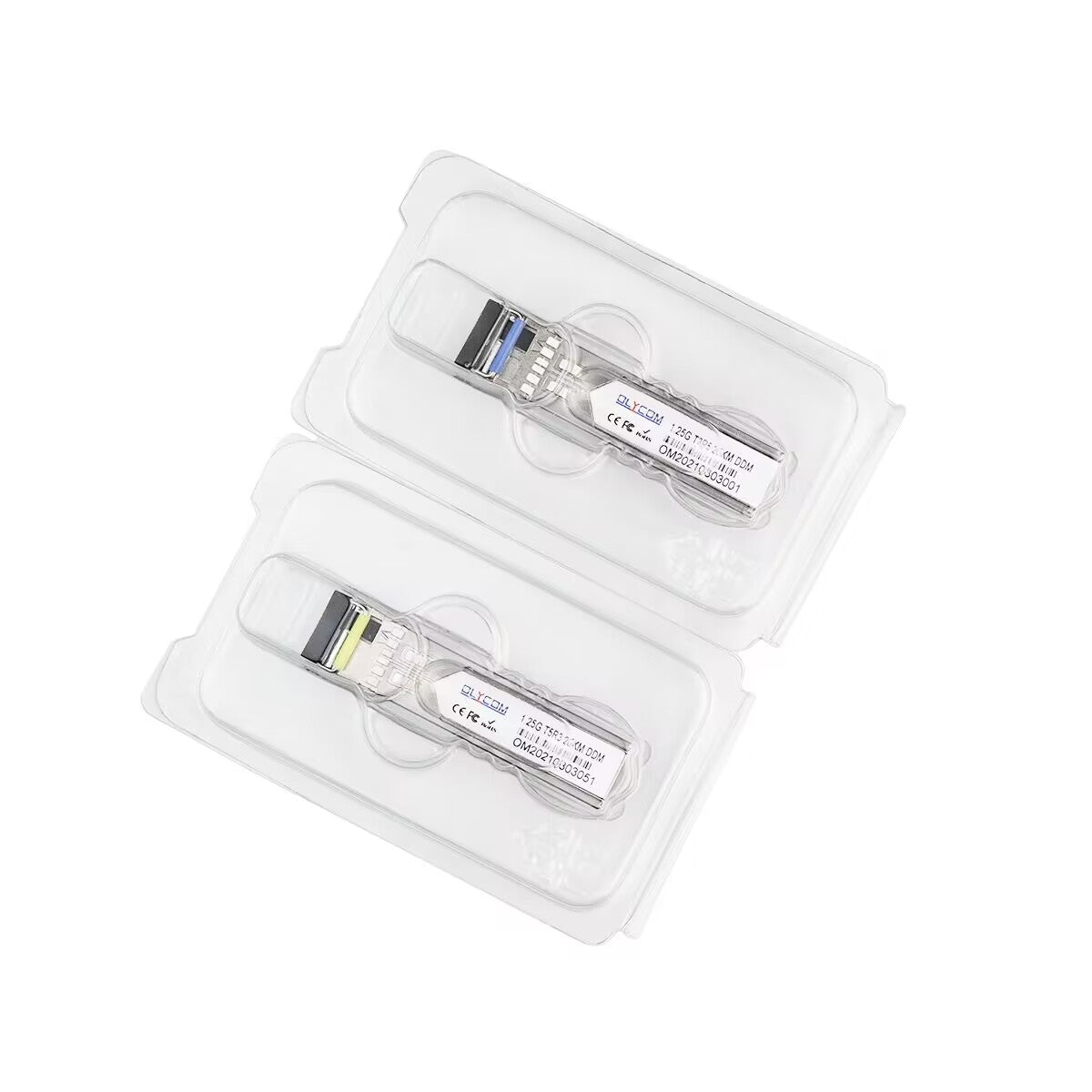
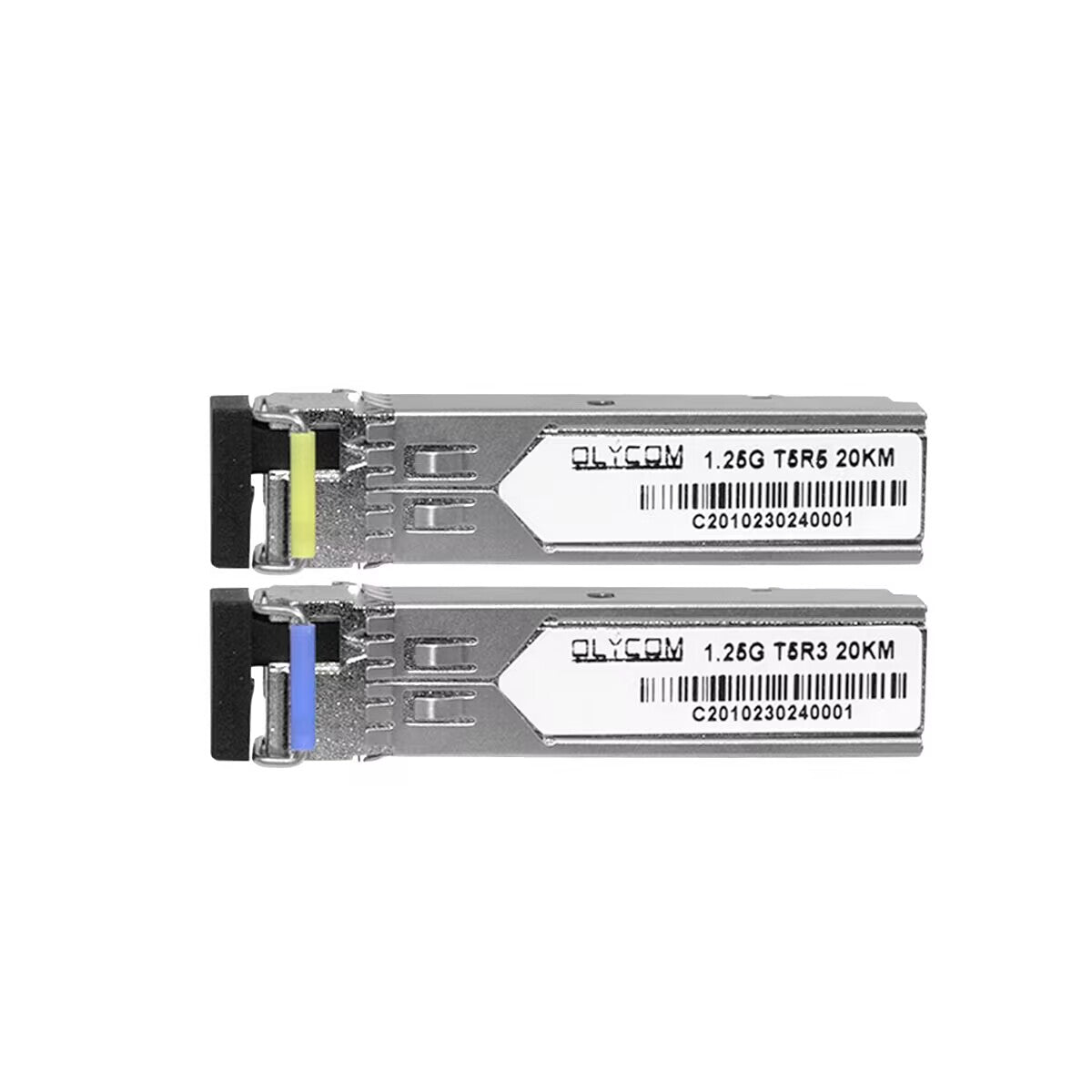
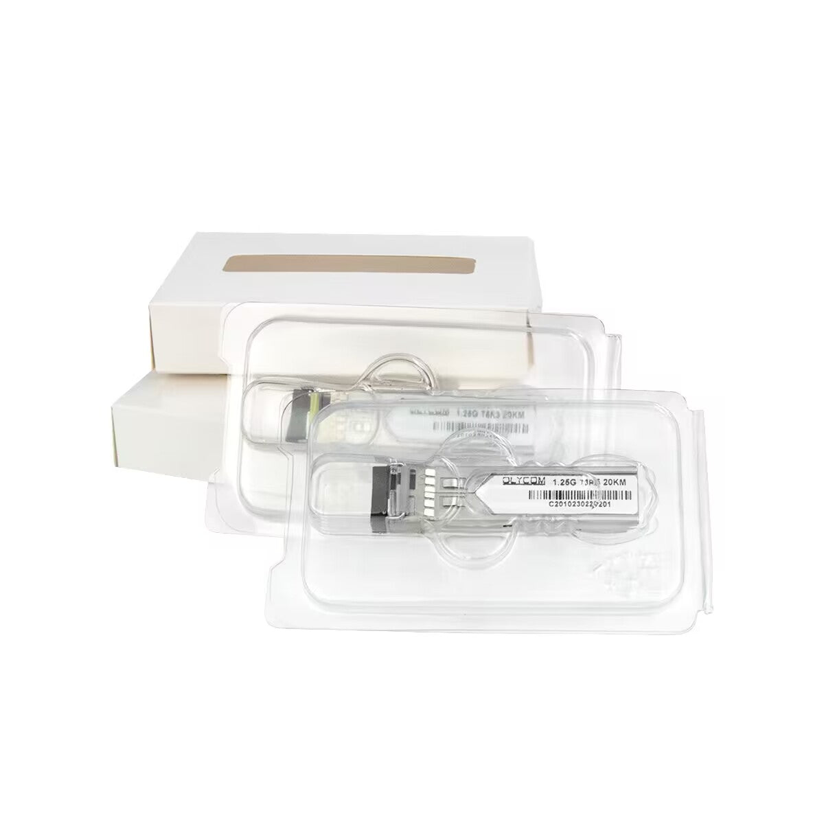
1.25Gbps SFP Transceiver, Single Mode, 40km Reach 1310nm TX / 1550nm RX,OSBL1G40D-35
1.25Gbps SFP Transceiver, Single Mode, 40km Reach 1310nm TX / 1550nm RX,OSBL1G40D-35
Couldn't load pickup availability
Product Features
Supports up to 1.25Gbps bit rates
Hot-pluggable SFP footprint
1310nm FP laser and PIN photo detector, Up to 40km for SMF transmission
Compliant with SFP MSA and SFF-8472 with single LC receptacle
Compatible with RoHS
Single +3.3V power supply
Real Time Digital Diagnostic Monitoring
Operating case temperature:
Standard: 0 to +70°C
Industrial: -40 to +85°C
Applications
1.25Gbps Optical systems
Gigabit Ethernet
1.063Gbps Fiber Channel
Other Optical links
Description
The SFP transceivers are high performance, cost effective modules supporting data rate of 1.25Gbps and 40km transmission distance with SMF.
The transceiver consists of three sections: a FP laser transmitter, a PIN photodiode integrated with a trans-impedance preamplifier (TIA) and MCU control unit. All modules satisfy class I laser safety requirements.
The transceivers are compatible with SFP Multi-Source Agreement and SFF-8472 digital diagnostics functions.
Notes:
1. The optical power is launched into SMF.
2. PECL input, internally AC-coupled and terminated.
3. Measured with a PRBS 27-1 test pattern @1250Mbps, BER ≤1×10-12.
4. Internally AC-coupled.
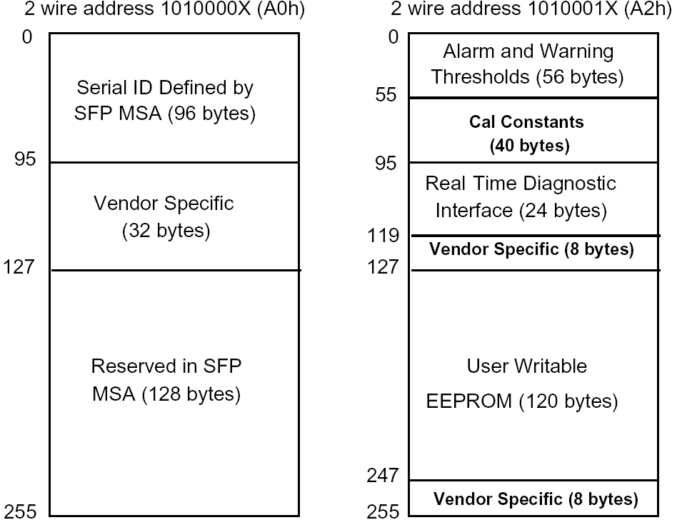
Digital Diagnostic Memory Map
The transceivers provide serial ID memory contents and diagnostic information about the present operating conditions by the 2-wire serial interface (SCL, SDA).
The diagnostic information with internal calibration or external calibration all are implemented, including received power monitoring, transmitted power monitoring, bias current monitoring, supply voltage monitoring and temperature monitoring.
The digital diagnostic memory map specific data field defines as following.
Pin Descriptions

Notes:
Plug Seq.: Pin engagement sequence during hot plugging.
1) TX Fault is an open collector output, which should be pulled up with a 4.7k~10kΩ resistor on the host board to a voltage between 2.0V and Vcc+0.3V. Logic 0 indicates normal operation; Logic 1 indicates a laser fault of some kind. In the low state, the output will be pulled to less than 0.8V.
2) Laser output disabled on TDIS >2.0V or open, enabled on TDIS <0.8V.
3) LOS is open collector output. Should be pulled up with 4.7k~10kΩ on host board to a voltage between 2.0V and 3.6V. Logic 0 indicates normal operation; logic 1 indicates loss of signal.
4) RD-/+: These are the differential receiver outputs. They are internally AC-coupled 100 differential lines which should be terminated with 100Ω (differential) at the user SERDES.
5) TD-/+: These are the differential transmitter inputs. They are internally AC-coupled, differential lines with 100Ω differential termination inside the module.
Recommended Interface Circuit

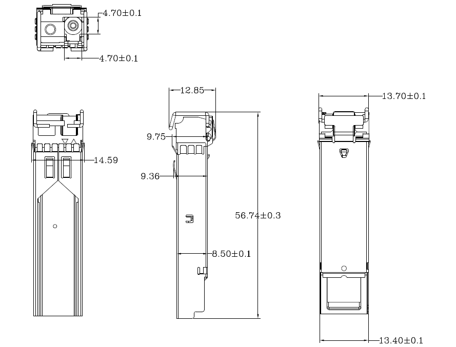
Mechanical Dimensions
Ordering information
|
Part Number |
Product Description |
|
OSBL1G40D-35 |
1310T/1550R, 1.25Gbps, LC, 40km, 0°C~+70°C, with DDM |
|
OSBL1G40DI-35 |
1310T/1550R, 1.25Gbps, LC, 40km, -40°C~+85°C, with DDM |